Thursday 30 December 2010

Winter Sports Kit

Well, the festivities have gone into remission for a day or two and my mind has switched back to the shack - not to address the boring software task which is the next step on the path to multi-band operation for the multi-mode beacon, but to get stuck into a good honest piece of mechanical work...

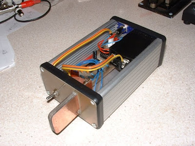
I had already completed the electronic side of the touch paddle - but it needed an enclosure to make it suitably robust to use in anger. I found an old Hammond enclosure, which once contained a small switch-mode audio amplifier which recently went belly up (I'm still not sure why). The donor enclosure even had a nice PP3 battery enclosure - but I needed to make a new "front panel".

The front panel has the job of supporting the paddle "blade", which is made of a sandwich of three pieces of PCB material. It occurred to me that soldering would be a good means of mechanical as well as electrical connection - so I decided to use similar fibreglass PCB material to make the new front panel.

Here's the system, without its lid on...


and this shot from the reverse angle shows how the "blades" are mounted...


Here's the finished article (with the rather more expensive "Bencher" paddle lurking ironically in the background)...


The new touch paddle partners nicely with my Funster Plus rig, to make the "Winter Sports" package seen below...


Also visible at the left of the lashed-together rig is a new, experimental CW filter I've been working on - more details to follow.

I enjoyed my first QSO with the new, boxed touch sensitive paddle with John, g4oyc and now have the opportunity to make a few more QRP contacts - with no moving parts!

...-.- de m0xpd

Friday 24 December 2010

One Step Closer to MultiBand

Today, making the best of a day off from the usual pattern of Fridays, I took another small step on the path to multi-band operation for the multi-mode beacon (Blogs passim). I had completed and tested the new bandpass filter (populated for 30 and 40m operation, with one as yet undedicated channel). Now it was time to install the new element in the box...

As the cold spell continues, work in my unheated workshop remains a non-starter. Accordingly, I had to drill all the new holes in the aluminium enclosure using a hand-held drill in the shack. That was going to be easy enough - but the bigger problem was with the marking out that preceded the actual drilling (all the measuring / marking kit is in the workshop and measuring, marking and centre-punching whilst balancing an object on your knee is hardly ideal). Fortunately, I had an idea...

Now - I'm sure this is "old hat" - but it had never occurred to me before. I could make full-size templates for all the boards (the new bandpass and the controller, which needed to be moved to accommodate the new board) in paper, using the Eagle PCB package with which the boards were designed. I printed them out and pasted them into the desired positions...


VoilĂ  - marking out done "automatically" - drilling the holes was a breeze!

Here's the bandpass board in situ, beyond the re-located controller...


Notice that I didn't bother to remove the paper templates - they're not doing any harm (in fact, they add a layer of insulation, potentially useful should anything - like a rogue nut - roll under the board and short to the case).

I also decided to take the opportunity to tidy up the power distribution arrangements - previously I'd just soldered more and more pairs of wires onto the tags of the 2.1mm DC Socket and things were getting awkward. Nothing that a scrap of Veroboard and a few Molex connectors couldn't handle. I even had the foresight to include two spare connectors (which will power the receiver and the switching output LowPass filter when I get time)...


It is working FB on 30m (I've arranged things such that the BandPass board "defaults" to 30m on power up). Now, I've got a pretty big/boring programming job to do to get the system running on 30 and 40m - adding to the menu system, switching the new bandpass filter and controlling the DDS. Just the sort of job to fill up a few quiet hours when I need time away from the fun, food and drink of the Christmas festivities - or from "Winter Sports"!

Talking of which, I am listening to "the message of the angels" from King's as I write. The last verse of the Processional (with Cleobury's descant) sounded a bit shambolic, I must say! Things can only get better...

...-.- de m0xpd


Update:-

Well, the service has ended and it certainly did not get better!

It would be interesting to know if the BBC OB crew were the usual (and usually excellent) "Choral Evensong" team - poor microphone placement could have explained some of the apparent timing issues. Otherwise, more questions will be asked of Dr Cleobury, who himself asked an awful lot of the trebles to follow him on his uncomfortable harmonic contortions in the "Adeste Fidelis" descant.

Finally, perhaps it would be kindest quietly to draw a veil over the dubitable liturgical design (not to mention the ordinary, secular nonsense) demonstrated by singing "Born this Happy Morning" at a quarter past four in the afternoon!

Wednesday 15 December 2010

WebSDR

Finding myself away on a business trip once again, with time to twiddle my thumbs, I decided to take another look at what can be accessed via the Hotel’s internet connection.

Regular readers of these notes may recall that previously I’ve played with “simulated” radio connections through HamSphere whilst in ZL and QSONet whilst in HB.

Well, today I’m back in HB-land but, rather than playing with web-based simulations of the ether, I’m listening to the action on the CW segment of 40m – the real thing.

All this is thanks to WebSDR, which is a network of public-spirited Hams, who make available a software defined radio, a server and some special code developed by Dr Pieter-Tjerk de Boer of the University of Twente.

There are several people offering WebSDR receivers as I write, as listed on the WebSDR.org homepage and shown in this map…


The receivers cover various bands – I’ve particularly enjoyed listening to Dan, yo3ggx’s system in Bucharest, KN34bk. Here’s a partial screenshot of the waterfall display on Dan’s page, running Pieter-Tjerk’s application …


This is useful, interesting and fun. Not just a great boon to travellers away from their own shacks but worth looking at from home too!

Thanks Pieter-Tjerk & Dan.

…-.- de m0xpd

Monday 6 December 2010

Touch Paddle

The "warm spell" yesterday allowed me to make not only the PCB for my band-pass filter for the multi-mode beacon (Blogs passim) but also a PCB for the experimental capacitive touch paddle.

An unaccustomed bout of insomnia had me up very early this morning and I took the opportunity to get the PCB stuffed and working - here's the new PCB sat next to the original breadboarded prototype (and using the same capacitive paddle "blades")...


I couldn't resist trying the paddle on the air - so hooked it up to my Funster Plus (which has an internal keyer) and called CQ.

I didn't get any replies for a while but heard Andre, f5ukl, calling CQ and I answered him. He gave me a 559 and has offered to send an MP3 of the QSO - so I'll be able to hear the Funster Plus AND the new touch paddle from the "far side".

Many thanks, Andre.

I have to say, I'm very impressed with the touch paddle - I'll put it into an enclosure and use it in anger - it might not have the charm and feel of mechanical paddles, but it sure was cheaper than the Bencher!

...-.- de m0xpd

Sunday 5 December 2010

Band Switching Arrangements

Having enjoyed little success with diode switching for the multi-mode beacon's band-pass filter, I've crossed over to a simple relay-based switching arrangement.

Each of the three bands in the unit under development has its input and output switched by a single-pole change over relay, as shown below...

The relays are switched by the circuit below (only one channel shown)...


I might not have used this design - but for the fact that it inherits much of its circuitry from the failed diode-switching circuit - indeed, I've actually stolen the components from the "diode" board!

The cold weather has been in remission today, such that I felt able to get out to the
PCB etch tank (which lives in what used to be the children's play house - now its just another "shed"). I made the re-designed PCB, drilled the myriad holes, populated and tested.

Here's the partially completed board...


I've populated two bands - for 40 and 30 m (these being the most popular QRSS bands at the moment). I've just got to wind and fit the toroids.

I'm going to leave the third channel unpopulated for the moment until I decide which other band to use.

The weather forecasters are suggesting it is going to get cold again - good job I got the PCB made today!

...-.- de m0xpd