Saturday 25 January 2014

"Open" QRP Transceiver

As somebody with more than a passing interest in simple CW rigs operating under the supervision of a micro-controller, I was delighted to have opportunity to investigate the "Open QRP Transceiver"...


This is a small, single-band CW rig - recently made available in the UK as a kit by Kanga.

The rig uses an ATmega micro-controller and a Programmable System-on-Chip (PSoC) to supervise operation of an otherwise traditional, analog transceiver. The transceiver boasts a superhet receiver and uses a single mixer to combine the transmit BFO and VFO signals, producing (in my build) 7.1 Watts of RF into the usual 50 Ohm load.

The digital components support a frequency display, a capable and comprehensive keyer and a morse decoder. This balance of digital features might be enough to give a clue that the rig has its origins with Steve, k1el, of Winkeyer fame.

There is a web page and a Yahoo group providing support for the design and the hardware details are available on the net (e.g. at the Kanga website). The code, however, is not openly available - a copy is given to all kit purchasers.

The Kanga kit is supremely well presented, with all the components packed into small zip-lock bags corresponding to the carefully designed step-by-step build sequence. This makes the assembly of what is a quite complicated and densely packed PCB very simple - as close as you can reasonably get to "painting by numbers". Furthermore, the staged assembly process is reflected in the layout of the board, seeing the builder start assembling sub-systems located in the middle of the board before going on to work on the periphery.

Here's the board at a fairly early stage of assembly (just after completing the VFO)...


I fell foul of what I believe to be an error in the kit; if you assemble the LCD display board according to the instructions, the LCD will not lie parallel to the font of the case (normal to the main PCB)...

 
On careful inspection, I realised that it is possible to fit the 90 degree header pins to the LCD according to (what turns out to be) an incorrect alignment, as seen in the sketch below at (A). It is important that there is clearance (c) between the plane of the pins and the surface of the LCD board (as at (B)) if the LDC is to fit.

To achieve this, I ignored the instructions and fixed the LCD to the front panel (taking due care to get the display aligned with the aperture) using insulating tape before soldering. Then I made a few soldered joints to establish position, took the assembly out of the case, and completed soldering all the pins. The overhanging pins sticking "backward" from the LCD module must be clipped off to avoid the Tx BFO crystal....


This was the only significant mechanical challenge I had to surmount in building the kit. However, I did have an electronic problem, which I've still not completely solved to my satisfaction...

On reaching page 24 of the build instructions, "Checkout of the Transmit Mixer", I was advised that I should have between 200 and 250mV pk - pk at U1 of the Transmit (SA612) mixer. Measuring it, I found only 115 mV. I was worried that this would cost me some transmit power, so I lifted up the VFO injection level by adding another 10pF in parallel with C16...


This gave me 220 mV at U1, pin 1 - in line with expectations from the instructions.

On completing my build of the rig, I've not been entirely happy with the stability of the VFO (of which more in a later post). However - my slight modification of the circuitry near the VFO has made people reluctant to accept that I had not brought my VFO into disrepute by my own actions! So - this morning, I removed the additional capacitor.

I'm back to 115 mV on U1, pin 1,  BUT I STILL GET 7.1W output.

Hmmm.

Here's the completed board...


It took me a day and a couple of hours of last weekend to go from a box of bits (in carefully sorted little bags) to a rig which let me have a QSO with f5ijy, op Phil, nr Dijon for 579 to 589. Phil said the rig was "doing a fine job" - so we'll take his word for it!

In summary...

This is a nicely designed transceiver, which has been very well presented as a kit. It is easy to build and results in an easy-to-use rig with some nice integral features (particularly the keyer).

Looking for a moment at some of the demerits, I would prefer a straight key input AND paddle input (which I fit as "standard" to all my rigs). I think that the Open QRP rig is unusual in using analog RF generation (going against the contemporary flow of the TenTec Rebel, Farhan's Minima and - not least - my offerings). You should not be fooled by the CW reader - which works well on strong signals, but which will not buy you out of the requirement to learn to read CW yourself! Most importantly, I don't think that this is truly an "Open" project (with the limitations on code distribution and the use of a proprietary PSoC).

In use, I retain some concerns about the VFO which, to date, has made the rig difficult to use in the ten minutes after turn-on. However, this is a very good way of getting onto 40m for what seems to me to be a very reasonable price.

...-.- de m0xpd

Friday 24 January 2014

Plumbing in the Filters

Having made and tested my new I2C-controlled filters, it was time to plumb them into the rig and go multi-band...

I made up some little patch leads from RG58, so I could plug the filters into the sockets that held the plug-in filters. That way - I supposed - I wouldn't need to make any modifications to the rig to incorporate the new filters. I should be so lucky!

 Here is the rig with the new filter boards patched into the signal chain...


On trying the filters, I noticed an immediate problem on 80m. As soon as I pressed the PTT or the key to put the rig in Transmit, the LowPass filter board tripped out - none of the filters was selected and no amount of subsequent band changing (thereby forcing my ATmega328P to send new commands to the MCP23008 IO Expander) would rescue things. I needed to "power cycle" - the new name for turning things off and back on again, for those who prefer to call a spade a personal, horticultural entrenching tool.

This was fixed pretty quickly by adding some more decoupling to the IO Expander chip - I already had 470nF about 2cm from the chip, but another 100nF right near the VDD pin and similar on the collectors of the relay drivers (on the 80m band only) soon cured things.

This fixed the LPF. However, plumbing in the new BPF was causing much greater problems...

Everything worked FB with the rig driving a dummy load. However, when I worked into my antenna system, I was seeing all sorts of problems on the meter on my tuner.

Looking at the signals on the oscilloscope soon identified the problem - the rig was generating out-of-band signals (at LOWER frequency than the intended RF). This was causing the indicated SWR to be very poor (which it was not; the antenna was correctly tuned for the band in question, but NOT for the additional lower-frequency content).

Eventually, I figured that this was caused by some kind of feedback path from the antenna back into the rig - which was sitting there naked on the bench, without shielding its modesty in a nice enclosure. With this differential diagnosis in mind, I set about looking for the source of my woes.

The out-of-band stuff was bad when I spoke into the rig and was strongly triggered by low frequency content in my voice. Conversely, a high frequency whistle seemed to provoke much less out-of-band output. This made me wonder if the feedback was somehow getting into the AF path - but careful investigation and measurement showed it was contained within the final stages of the transmitter.

Eventually, I discovered that things were made very much better if I removed one particular segment of wire on transmit, seen here labelled accordingly...


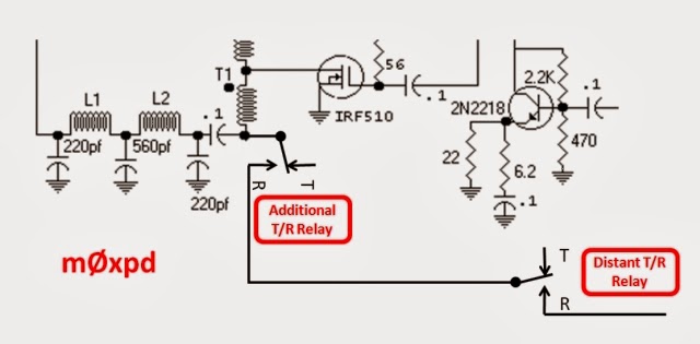
The offending wire (in fact, a length of coax, some 10cm long) was driven at one end by the PA output during transmit, BUT WAS OPEN CIRCUIT AT THE OTHER END, due to the action of one of the Transmit / receive relays. 

Here's the relevant section of the schematic...


I decided that the quickest path to a solution would be to add another little relay close to the final transistor, in series with the one already there, such that the little piece of wire is automatically removed whenever the rig is in transmit. Here's the plan...


And here's the actual fix on the rig...


Strangest thing of all - I'd been supported and encouraged through some of this fight with the RF feedback by my friend, mentor and collaborator (watch this space!), Pete Juliano, n6qw. Turns out that he's had a VERY similar problem in his build of a BITX20 - which he solved by adding an extra relay too.

Now, the rig works on all four bands, without having to do anything more than drive the menu system on my "VFO". Of course, I still have to adjust my antenna and (of course) the g5rv is still little more than a dummy load on 17m but at least the rig is now genuinely multi-band.

As I admitted before, things are not yet "perfect"; I still see faint traces of the original problem (which TOTALLY disappear when firing into the dummy load) but I'm not going to do any more detective work to improve matters until the rig gets a properly shielded enclosure. It is entirely usable now.

Instead of wasting time chasing perfection, I'm off to explore four different bands at the "flick of a switch"!

...-.- de m0xpd

Friday 17 January 2014

Farhan's New Transceiver

I'm excited to see that Farhan has used digital RF generation and (Arduino) micro-control in his new rig, the "Minima"...


I particularly like the under-stated name; I'm sure little Minima is going to generate a big noise in our hobby.

Congratulations, Farhan - you've fathered another beautiful child.

 ...-.- de m0xpd

Sunday 12 January 2014

Low- and Band-Pass Filters

I have just completed the new I2C controlled low-pass and band-pass filter boards for my multi-band rig...


Despite my experiments with the MCP23017 last week, I'm using the Mircochip MCP23008 I/O expander to control four filters, one of which is switched into circuit by relays. The switching is controlled by I2C messages from my RF Generator, which is in essence an Arduino.

I have used a common board layout for switching part of the system and inserted band-pass and "harmonic" filter networks, both of which are to standard G-QRP Club recipes...


There are jumpers to set the I2C address of each board - but in use they will share the same address, such that both MCP23008s respond simultaneously to the band-change request. The I2C input (which also supplies 5V power) is at the left of each board, whilst the relays are switched by 12V, supplied by an input on the opposite side. RF enters the boards stage right and leaves on the left.

The boards are only single-sided PCBs, made in my "back-yard PCB fab", so I had to add some additional wiring on the copper side to control the output relays...


In use, the boards will be stacked, in an attempt to save space - it worked for the Tokyo city planners. Here's the intended configuration...


I have built filters for 80,40,20 and 17m - the first three are my favourites on the new rig and the 17m band is an experiment.

The system works FB - but I haven't yet had chance to plumb it into the rig - I've run out of weekend, not helped by spending a couple of pleasant hours at the West Manchester Club's "Red Rose" Winter Rally earlier today, where I didn't do any significant damage to the bank account.

...-.- de m0xpd

Wednesday 1 January 2014

Switching Band-Specific Elements

This post describes some initial experiments to add extra GPIO pins to the Arduino using a Microchip GPIO Expander.

My band-specific plug-in modules (as used on my multi-band BITX and Occam's Dagger rigs) are all very well...


But - let's face it - plugging and un-plugging is hardly in the spirit of the rest of the micro-controlled system.

With the Christmas and New Year festivities fading into memory, it is time to get back to the bench and play some games and the idea of switching band-specific functions (like low- and band-pass filtering) had bubbled up to the top of my list. It is a game I've played before - but this time I intend to have the filter board respond to I2C commands, rather than a parallel digital input.

In all my "Arduino" controlled rigs, I've already run out of Input/Output pins - so it was my intention to hang an input/output expander chip on the I2C bus. Whilst there are other devices available, I planned to use the Microchip parts and had ordered an MCP23017 device to play with a few weeks back.

There are good resources on the internet teaching you how to use this part - I used and recommend the excellent tutorial here.

Before I could do anything, I needed to be able to parallel the I2C lines with the LCD module - so I made up a little scrap of stripboard which allows me to hang three devices on the same "bus" (comprised of power, clock and data lines)...


The MCP23017 was plugged into a solderless breadboard, which also housed a single general-purpose NPN transistor (in my case a 2N3904) to switch a little relay. Here's the breadboard...


and here are the DPDT relays I intend to use when I get round to building permanent I2C-switched filter boards...


Coding for the GPIO expansion is very easy (see the tutorial in the link above).

I set up an array of "codes" which I want to write to the GPIO device...


This array will be used to assert one of the GPIO device's outputs for each band - the asserted output will turn on the transistor which will in turn turn on two relays to patch in the intended band-specific filter. One of these transistor / relay combinations was implemented on the breadboard (above) for my experiments.

My software (both for the "Occam's Dagger" CW rig and the subsequent BITX SSB rig) has an integer variable describing which band is in use - so this variable is used to index into the BandSwitch array to choose the appropriate code for the GPIO device. However, before the device can be used, it must first be initialised...

The GPIO device has three hardware address pins, which are tied to 0 or 5V to set the I2C address. My LCD is already on address 0x20 - so I had to select something different. Setting all three address lines high gives an address of 0x27 (you can learn about this in the tutorial if you're not au fait with I2C). With the address defined, initialisation is simplicity itself...

You use the Arduino "Wire" library to talk to the GPIO expander. You need first to specify if the ports are to be used as inputs or outputs - in our case they'll be outputs. I am only going to use up to 8 bits but in the following code, I set all 16 of the available pins on the MCP23017 as outputs.

This "initialisation" code should appear in the "setup" phase of the Arduino sketch - in my case I added it at the very end of "setup"


The code also sets the GPIO outputs to that appropriate for the initial band - in my code the band in use is described by the value of MenuOption[3], so BandSwitch[MenuOption[3]] is the code relevant to the starting band.

Subsequently, whenever the band is changed (i.e. when MenuOption[3] changes value), the following code should be called...


This can be added into the code that runs as a specific action on leaving menu mode after a band change.

Here's the whole shebang on the bench...


I found that one relay coil draws 18mA from the 12V supply - so I anticipate that the power consumption of the whole rig will go up by around 60mA when the bandswitching is fully automated.

Here's a schematic illustrating the "spirit" of my experiment - it uses an MCP23008 rather than the MCP23017, but that's what I plan to use eventually.


Now to design some filter boards.

.... -. -.-- de m0xpd