Sunday 28 June 2015

Nokia 5110 Display

I have been playing with a little monochrome LCD display, of the sort used in the original Nokia 3110 and 5110 phones...


I was interested to see if this kind of display technology would be of any use for the "Occam's Dirk" rig, when packaged up for mobile applications.

It was the overall size of the 20*4 alphanumeric display I had used before that was tempting me to consider an alternative - not the sense that I needed to display any more information - quite the opposite, in fact. This diminutive unit seems just the thing.

Unfortunately, there were two obvious disadvantages to confront - and one surprise! We'll deal with the obvious disadvantages first...

The old alpha LCD unit interfaced to the Arduino via I2C, which has no "cost" on the pin allocation, since the I2C interface is already used (in the Occam's Dirk rig) to talk to the Si5351 RF generator. Switching to the new Nokia LCD requires four or five pins - PROBLEM!

What's more, the little Nokia display talks in 3v3 logic language, whereas the Arduino UNO is running with 5V logic, so interface requires a level converter on these four or five pins. Not exactly a problem, but at least an inconvenience.

Some people use the 4050 as a level converter - but I decided to press into service one of my Octuple level converter plug-in modules to experiment with the screen.

I looked around on the internet and soon found the Adafruit Nokia library, which calls upon Adafruit's GFX graphics library (with which I was already familiar after having played with a color TFT screen).

I played around with the screen under the "pcdtest" example which Adafruit supply with the library and verified that all was working FB.

Unfortunately, when I tried to include the libraries with the Occam's Dirk program, the resulting code was too large to load onto the little microcontroller, so I decided to abandon the easy library approach and tried instead to use a bit-banging solution, borrowing from code found at Sparkfun and on the Arduino site.

After a while, I had the code ported to the new smaller display format and working well...


The display is fast compared to the ponderous old 'Hitachi' LCD device on the far side of the I2C-to-parallel module that piggybacks on the LCD.

Unfortunately, there was cost in porting the code - I had to lose the automated CQ calls in order to generate enough memory space to fit everything in. Still - this is a luxury I can do without.

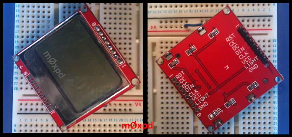
The test set-up for development (on a breadboard) is seen here...


I did the coded development on a spare UNO and just had a tuning plug-in connected (so I could drive the user interface).

Once ported over to the Occam's Dirk rig itself, the whole system is now pretty small - ready to be packaged in a small "trail-friendly" enclosure...


For reference (mine as much as yours!) here's the allocation of the I/O resources on the Occam's Dirk rig, with the new Nokia display...

0 (Comms)
1 (Comms)
2 RotEncoder
3 RotEncoder
4 leftButton
5 rightButton
6 ditPin
7 dahPin
8 str8Pin
9 sideTonePin
10 RxMute
11 SCLK (Display)
12 SDIN (Display)
13 TxKey
A0 RESET (Display)
A1 DC (Display)
A2 SCE (Display)
A3 RotEncSwPin
A4 I2C
A5 I2C

I ran the display successfully with its reset line connected (via level conversion) to the Arduino reset but, since I had already been forced to abandon the automated CQ calls in software, I decided I may as well use the I/O line that was assigned to the switch that used to trigger them for an explicit software-controlled reset function for the display. If ever I reinstate the automated calls (or need an I/O line for another purpose) I can go back to the hardware reset.

Once I have had opportunity to tidy up the code (and if there is any interest) I might be persuaded to release a copy of this new version of the software. Certainly, my initial impression is that the cost of the pin-count congestion and the code congestion might even be worth it - the display looks and responds very nicely.

...-.- de m0xpd

Sunday 14 June 2015

Patriot Games

I came home from Dayton to be presented with a TenTec Patriot, all thanks to my friend and benefactor, g6ybc...


The Patriot is a QRP CW and sideband rig for 40 and 20 metres, built on the ChipKit UNO 32 platform which, although it is based on a Microchip PIC processor, is approached through a Development Environment compatible with that of the Arduino. This makes the system more accessible for amateur programmers and - obviously - has some significant links to the work I've been doing with my Occam's Microcontroller project.

The Patriot is a development of TenTec's earlier "Rebel" CW rig. Both the Rebel and the Patriot are genuine Open-Source projects; both the hardware schematic and the code are published on-line and there are active user groups supporting these products. Indeed, without the user group, it is difficult to see that the product would be viable...

The Patriot is delivered with just a simple printed user guide - no connectors or accessories of any kind. Fortunately, all the connectors are pretty standard, as seen on the photo of the front and rear panels below...


Regular readers will know that microphones are about as rare as rocking horse poo here at m0xpd, so finding a mic for the new rig was always going to be a problem. Harder still was the 8-pin plug it is connected with (a TenTec standard, apparently). Sideband operation would have to wait - I would try CW first.

The rig has the usual stereo (tip-ring-sleeve) 3.5mm jack socket for a paddle input but the code supplied with the Patriot (as delivered) only supports a straight key or external keyer.

I was disappointed to measure that the power output on CW was only around 1.5 Watts, despite the 5 Watt claim in the specification. Ever since getting back to the UK, the bands have been in pretty poor shape and I have been dogged by QRM - so I wasn't too surprised to find it difficult to make an initial contact with this 1.5 W. But I WAS able to connect with other rigs of similar power - so, obviously, something was wrong...

On investigation, I found that something was, indeed, very wrong. The code as delivered appeared to have completely ignored the CW offset, such that when I was tuned to a station calling CQ, my reply was so far off as to be inaudible to the far-end station. The only way to get the situation close-to workable was to have the RiT control at maximum offset (full clockwise on 40, full anticlockwise on 20, I think it was - I can't now remember!). Even this didn't quite get to a "zero beat" - but, at least, I could make some contacts.

I decided to look into the code, so I downloaded the development environment, MPIDE, delighting at how compact it was compared to the ludicrously long downloads we are now being offered from the various offshoots of Arduino.

The IDE is familiar to anybody who has played with an Arduino before - so I quickly made modification to the band limits to make sure I didn't offend the terms of my license...


I also confirmed that there was indeed no attempt at sorting the CW offset and wrote a modification to include it. It took me an age to get this modification to work (because of another "blooper" in the code, which took me a while to spot), but eventually I had the CW offset sorted to my satisfaction.

These code changes are programmed into the rig through the USB connection on the rear panel, seen in the photo above.

Despite the terrible band conditions, I've now been able to have QSOs on 20 and 40, best of which was to Bandi, ha5aek, in Budapest.

The Yahoo users group, who I've now joined, seem to have spotted the CW offset issue and (no doubt) have a fix for it in their code.

After a few days' wait, a bag of three 8-pin plugs (technically they are line sockets, but we all know what we're talking about) arrived from Jan and Sandra of The Norfolk CB Shack...


No affiliation - other than the pleasure of trading with people who will send me three plugs for pretty much the same price everybody else seems to be asking for just one.

I was soon able to knock together a little microphone with a junk-box electret insert and a tactile switch...


A whistle into the mic causes the rig to put out a measured 4 Watts on 40m (although I haven't made any adjustments to the little "Mic Level In" preset on the side of the case).


Again, the bands haven't been collaborating since the arrival of the microphone - but I did manage a quick exchange with Sergey, ra1any, in St Petersburg on twenty metres yesterday. He gave me 5 and 5.

There's a lot more to be done, of which the priorities must be to hook up some kind of frequency display, to implement a keyer and to get the power on CW up to closer to the full gallon. But my first impressions of this little rig are positive enough.

Hardly surprising - they are preaching to the converted!

...-.- de m0xpd

Monday 8 June 2015

Handling two DDS Modules in the Library

I had an email today from Jan, pa0dmm, who has been using my library for the AD9850 DDS.

Jan wanted to know if it was possible to modify the library to control two DDS modules, such as I have done on my R(F)Duino Board...


and in the Parallel IF rig.

In answering Jan's question, I realize I've never really addressed this point before - so here's a quick post to explain how it is done.

First, I don't feel a modification to the library is justified - the present library can be used to control two instances of the DDS module, as follows...

First, the pin allocations have to be made. These are arbitrary - for example my rig uses...


Notice that the DATA and RESET lines will be shared between the two modules - only separate "W_CLK" and "FQ_UD" lines are defined, making a total of six digital lines to control the two modules.

Once the pin definitions are made, the DDS classes can be instantiated - one for each of the oscillators. Notice they're given a name associated with their intended application (Jan intends to use them in a superhet - just as I have)...


Once they are instantiated, they must each be initialized and (if you are being fussy) trimmed...


From this point on, you are ready to go, with two independent oscillators being addressable from your code with the simple frequency setting method provided by the library...


I honestly hadn't remembered that this approach wasn't one of those in the many examples shown on the Double_DDS page - evidently I was trying to preserve some simplicity there (before becoming distracted by the Si5351).

Hopefully this post makes up for my omission and will help anybody wishing to use the library with multiple DDS modules - as I have done with my own rig!

...-.- de m0xpd

Sunday 7 June 2015

Meeting a Master and a Masterpiece

Any QRP enthusiast and CERTAINLY any home-brewer should know of w7el's "Optimized Transceiver for 40m"...


It is a beautiful piece of engineering - one of the few places where the word "Optimized" is appropriately used (as the design shows - in several places - clear evidence of intentional engineering optimization).

It is a masterpiece.

I stole from it unashamedly in my Funster Plus, believing the VFO and the receiver in particular to be difficult to beat. I also used the design as the inspiration for the first of the "Occam's" receiver shields.

I had the particular pleasure of meeting Roy, w7el, at a Rishworth mini-convention a few years back - and I thanked him for his masterpiece then. But at the recent Four Days in May, I had the greater pleasure to go one better...

After mentioning the Optimized Transceiver during my presentation, I saw the masterpiece - and even held it in my hand!


I heard the story of its creation (as evolution from a VFO) and marveled at  the density Roy had achieved - it sure is small!

There is a widely held view that one should never meet one's heroes. That's a pretty depressing sort of attitude. With heroes like Roy, it is a fallacy, for w7el is a charming man - the sort of hero one ought to meet.

He is a resident of the beautiful state of Oregon and a fly fisherman - both of which immediately endear him to me and both of which would have been immediately evident to you if only my photo were sharper...


That meeting - with a Masterpiece of RF Engineering and with its quiet, charming, Masterful Creator - was the highlight of FDIM 2015 for me.

...-.- de m0xpd

Friday 5 June 2015

Dayton

After a few self indulgent posts of what n2cqr would call "travelogue", its time to post some more useful material about Dayton - particularly as I'd made a fool of myself by speaking at the Four Days in May event...


Those of you who showed the good taste to miss my presentation can at least download the materials from this site.

There is a copy of the written "paper", which was printed in the conference "proceedings".

There is also a copy of the PowerPoint slides I used as backdrop to my presentation - although many of the animations and transitions will make precious little sense without my words over the top - the slides are just the "backing track". That's not to suggest they made much sense with my words over the top!

The presentation was recorded on video and will be made available on-line at some point. I'll add a link to make my embarrassment complete when such a link becomes available.

For any that don't know, QRP-ARCI's "Four Days in May" runs concurrently with the Dayton Hamvention.


Both events are a must-see for QRP enthusiasts, in my opinion. The social side of FDIM is particularly enjoyable.

I believe these are coffee mats - but they may as well have been beer mats, as there was quite a deal of business conducted in the bar!


The Hamvention - which is based on the other side of town, some thirty minutes' drive away from the FDIM Hotel, is vast.

The indoor spaces include trade stalls from ALL the major manufacturers and all the important groups and Societies, such as our own RSGB...


Mrs m0xpd was even running the G-QRP stall single-handed at one stage!

As well as the big players, smaller manufacturers are present too, including American Morse Equipment, from whom I purchased the little paddle kit mentioned in a previous post...


When you're done with the indoor stalls, you can go outside to the Flea Market - where you need to be prepared with all the American superlatives ("Awesome" etc) you can muster - for it extends further than the eye can see (and much further than my legs or my patience could carry me).

Here's a shot of one random line of parked-up dealers, plying their trade...


Whilst I appreciate that not everybody is able to get there (it is expensive and inconvenient) FDIM gets my very highest recommendation. I had a great time.

My special thanks to Steve, g4gxl, to all my friends at G-QRP, to Rex, w1rex, to Tom, wb8lcd and Chuck, w8pt and to all the other folks I enjoyed meeting and talking with.

I shall certainly be there next year!

...-.- de m0xpd

Wednesday 3 June 2015

Ham Radio in Laramie

I arrived back home yesterday from my trip to the US, my jeg-lagged mind awash with memories of new friends and great experiences. I met a great bunch of amateurs in my old stomping ground in Laramie, WY...

First, I met a few hams at my talk at the University, where I spoke about the Physical Computing movement and its implications in STEM outreach, Teaching and Learning, and Curriculum Design.


Bob, n7cii, is a faculty member and it was great to meet and chat with him - particularly as it turned out he had my old office and had graced it with a copy of EMRFD!

Walt, k7se, also came along to the talk - he was to become a good friend throughout my visit, being honoured at the "Bernie Club" BBQ, which Lou, wy7ls, President of the University Amateur Radio Club, had arranged in Washington Park.

Several local hams gathered for burgers, hot dogs, chicken, etc and a good chat...


Seems that "Bernie" (from which these gatherings take their name) was a ham from the nearby Colorado town (no doubt the locals would call it a city - any U.S. setlement of more than three or four inabitants is a "city") of Fort Collins.

I had a great evening, learning that the dominant activity of the club is in provision of VHF communication services for community events (such as bicycle races), which, as well as being a useful and enjoyable activity in itself, provides a framework for the provision of a similar service, should it be needed in emergency or extreme weather conditions.

Walt was celebrating 60 years of "radio activity" during my visit, so a cake was produced, cut and enjoyed - you see Walt, his wife Dolores, ka7mpb and the cake below...


Also seen in the photo above is Scott, who remembers me from the time I was a young Faculty member at UW back in the 1980s - seems I was his advisor when he was a transfer student. I apologised and said I hoped I hadn't blighted his life too badly. We were able to enjoy pleasant time together - so it seems my sins were forgiven.

I was lucky enough to be invited out to Walt's place N of town, where he has a great shack, optimised for his passions of DX-ing and contesting (apologies for the poor "phone" photo)...


His 30 acres on the prairie allow antenna farming on the scale I can only dream of - and you can see the clear blue skies of Wyoming at a mile and a quarter altitude that I still do dream of...


Walt gave me a leaving gift of surpassing generosity, which must be recorded...


I met a great bunch of hams - but I'd like to thank another ham who I didn't meet. Both before and during my visit, Dale, wc7s, down in Cheyenne, had provided a bunch of information and inspiration about radio in the Rocky Mountain West and and WY in particular. Thanks Dale - maybe next time!

If ever you're fortunate enough to be in the West, get in touch with these guys and gals.

...-.- de w7/m0xpd