
Since signal processing is so computationally intensive, we tend to associate it with powerful processors, like the mighty ARM of the DUE. However, it is entirely possible to do useful signal processing tasks - such as running digital filters, or even performing Fourier Transforms - on humble little processors like the ATmega328 on the Arduino. These past few days I've been doing just that.
The application is within music - specifically, on my new modular synthesizer. But don't look away just because you might not be interested in music, for underlying this is an entirely general application of real-time programming.
My synthesizer already had (as you might have seen) a couple of envelope generators, capable of producing exponential 'attack' and 'release' envelopes at the edges (or at the beginning) of a gate pulse. However, I wanted a more traditional 'ADSR' envelope generator with the capability to generate independent control of three time constants: attach, release and 'decay', as well as to manage the amplitude of a 'sustain' phase.
This type of circuit needs two core elements:
- a first-order circuit with three controllable time constants
- logic to switch between the three exponential decay phases and manage the 'sustain' phase.
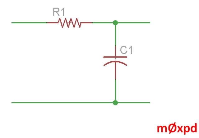
It struck me that - given the requirement for the logic around the analog filter, the entire system might be better implemented by a micro-controller, replacing the analog 'filter' with its digital equivalent.

I certainly don't claim any novelty in this thought - indeed, it was reading about Tom Wiltshire's excellent Digital Envelope Generator which motivated me to give it a try. But the experiences of doing some more work back in PIC-land last week (more of that in a later post) reminded my just how dry and tedious that place can be, so I set about trying it on the homely little Arduino.

Neither do I claim any novelty about the idea of doing it on an Arduino - somebody/several bodies must have done it on this platform before (indeed, I got a first version running using ADSR() from Mozzi, but I didn't like that for several reasons, most important of which was management of the sustain phase). Anyway, whatever the reasons, I wanted to have a bash for myself.
Let's take a look at my code first.
Here's the core first-order difference equation which - in any of the phases of operation - produces the required exponential envelope...

If you don't understand the math behind this stuff don't worry - you can read about it in a book if you like - or you can just be content to use the results. I've written the difference equation in the comment above in something close to 'conventional' notation, for those who do understand these things.
That was the first of the two 'core elements' - the digital filter implementing the exponential response. The second part is the logic. Here's a snapshot of part of that logic...
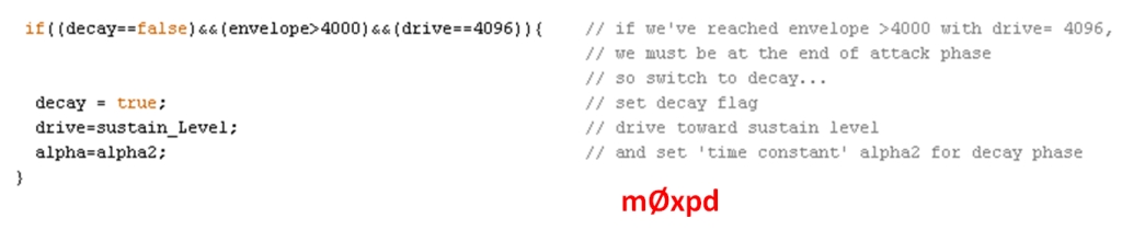
To be precise, it is the part of the logic which tests if the envelope is at the end of the attack phase. If it is the end, new values of 'drive' and 'alpha', relevant for the next phase - the decay phase - are loaded.
Enough dry talk of the inside of the code - if you want to see it all, you can download it from this github repository.
I had to give it a name and I followed the rather childish practice of choosing names which pick up on the involvement of the Arduino: 'ADSRduino'. Sorry.
Instead of talking, let's see some action.
You probably weren't impressed with the rather quantized image at the top of the post. What you didn't know was that entire envelope was less than 10ms long (shown in order to demonstrate that this system is appropriately fast - in fact, the sample rate [that's to say, the rate at which the difference equation is operated] is around 3.3kHz).
Here's a longer event (around 400ms long) along with the gate pulse from my keyboard which triggered it. It leaves time for envelope to move through the quantization steps of the DAC more slowly, making for a smoother trace.

Here's the same thing, annotated to make it clear what all this is about:
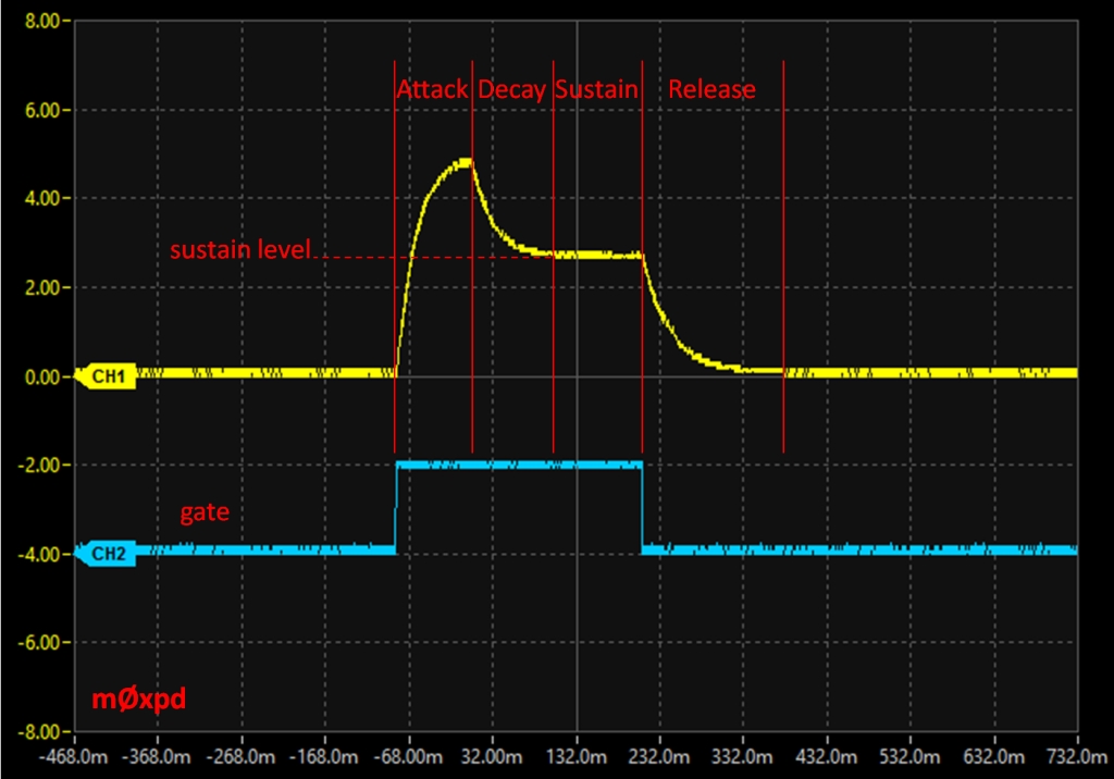
You can see that the attack phase starts when the note is gated and rises up to full value (actually 5V) then falls down in the decay phase to the sustain level. The note is sustained until the gate is released (unless it already has been released), after which the release phase begins.
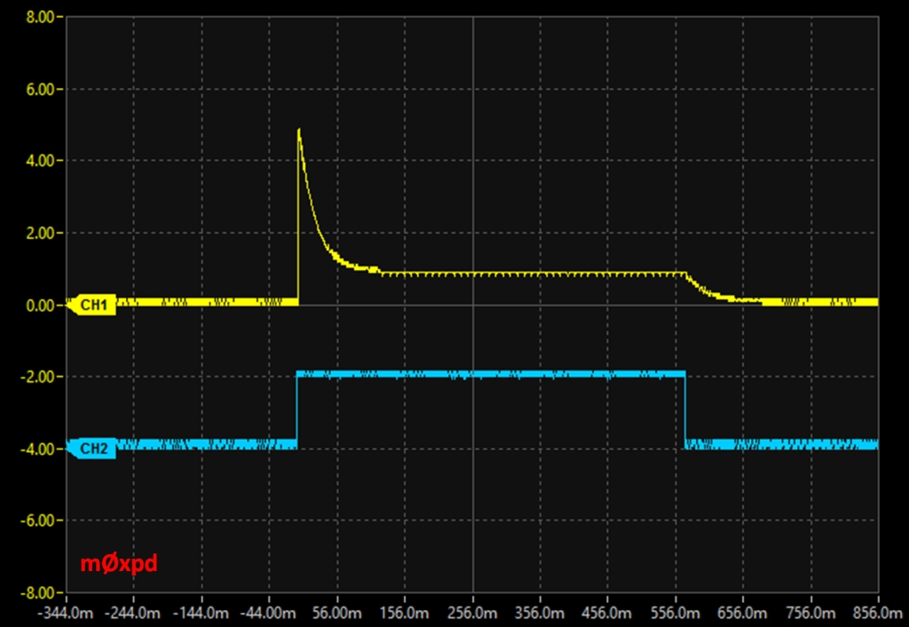
The time constants for attack, decay and release - and the level for sustain, are adjustable via user potentiometers. To illustrate the point, here's another setting (with fast attack and lower sustain and, as it happens, I pressed down the key for longer, so the gate pulse and associated sustain phase is longer):
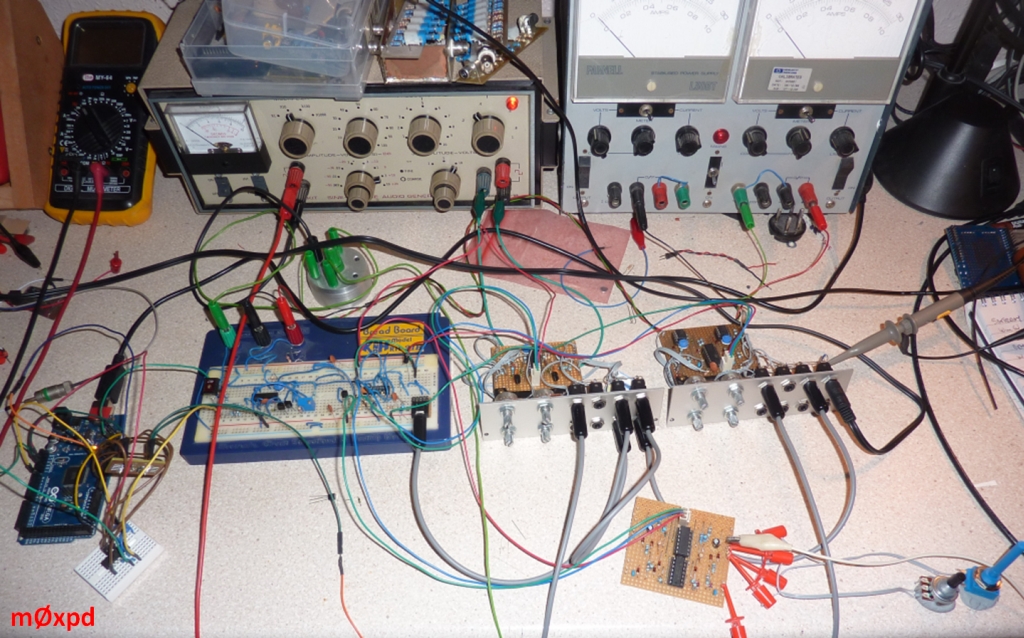
All of this is actually running on useful hardware. It started as a prototype on an Arduino UNO and then migrated onto a physically smaller NANO, which is seen here...
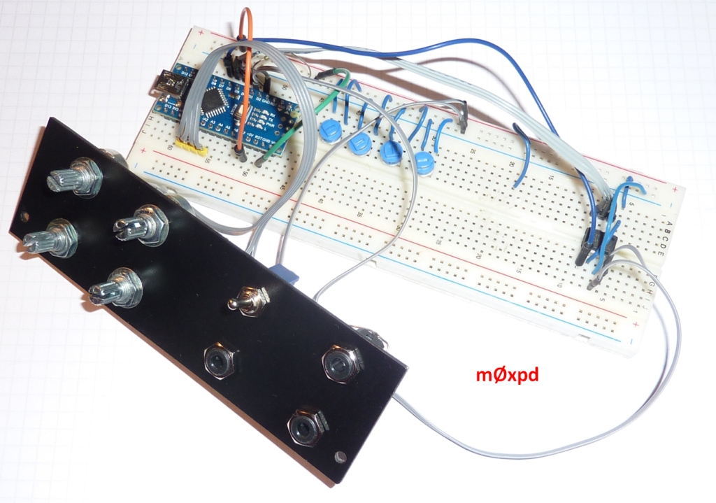
You can see both the original trimpots used for the ADSR controls and the new potentiometers on a front panel (made from double-sided copper-clad board, painted black to make it look fancy) - as well as sockets for the gate input and the output. There's also a switch to select a looping mode, in which the system can automatically re-trigger itself.
You can also just see (at the right-hand end of the breadboard) the little MCP4921 12-bit DAC used to output the envelope voltage.
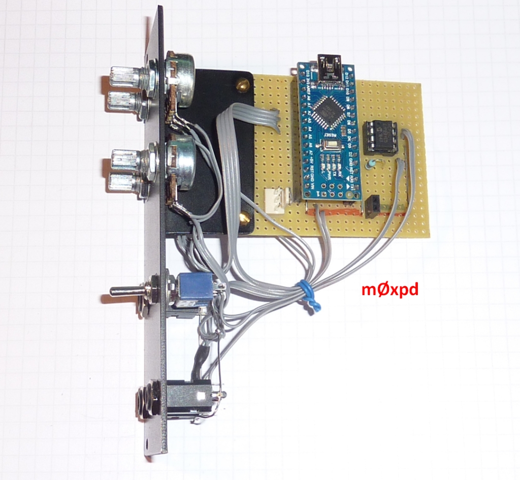
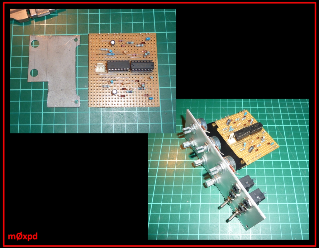
The circuitry above was moved onto a piece of stripboard:
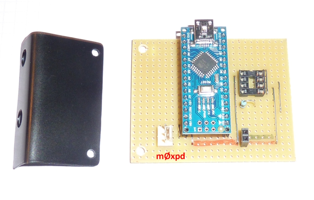
and assembled, using the bracket bent up from sheet steel, into a complete 'Eurorack' module:
You can find a schematic for the whole system here
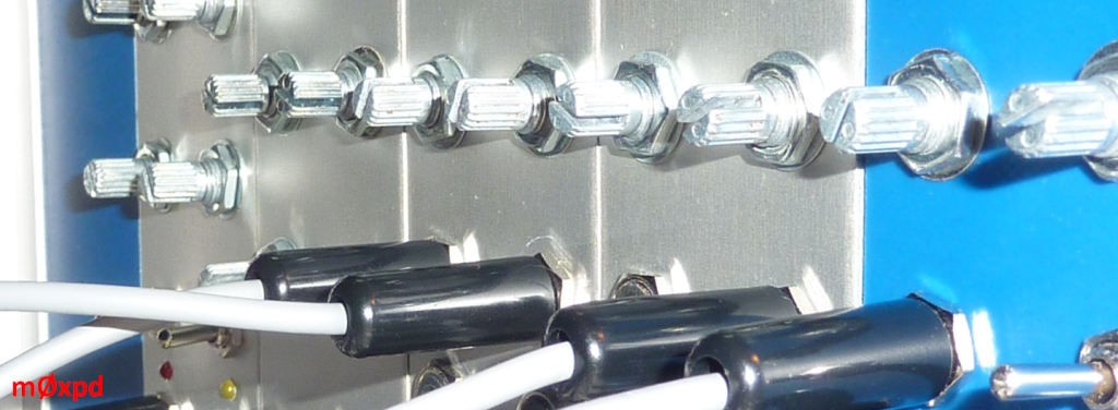
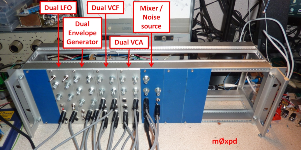
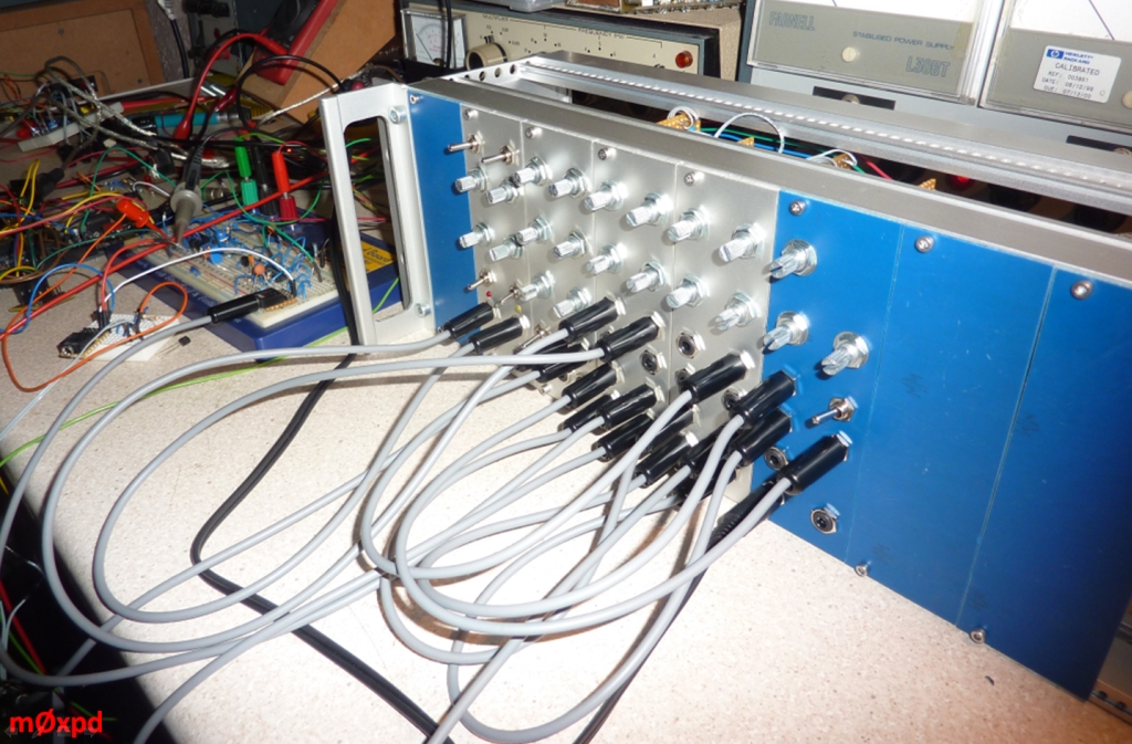
It now does great service in the considerably extended modular synthesizer:
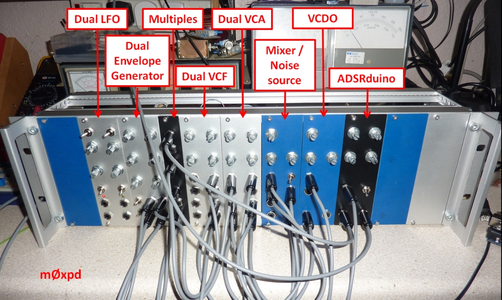
where it sits next to another Arduino-based module, running as a voltage-controlled digital wavetable oscillator, built upon resources from the Mozzi library.
Of course, as I mentioned at the top of this post, you can take the signal processing ideas on the Arduino further than first-order. I've been playing with a biquad structure on the Arduino within the loop() function...
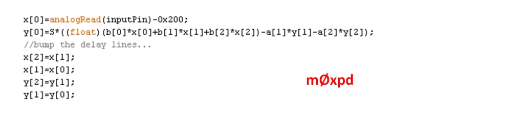
(in which all the elements have their usual meaning). I found that it is easy to achieve a sample rate of 2 kHz which - although it isn't useful for audio frequency work - does make for some very useful filtering for signal detection etc. If you need to detect or monitor AF signals, the Fast Fourier and Hartley Transforms work very well at sample rates of tens of kHz - but that's a rather different kettle of fish.
Don't overlook the little ATmega328 when you're playing with a time-varying signal that takes you to the edge of a DSP application. You can run some genuine digital filtering algorithms (including floating point math to manage poles right up close to the unit circle) and have fun in the process.
...-.- de m0xpd

